ISNO Super
A board built for radio firmware, so you can stop stacking CC1101 modules on a breadboard. Two sub-GHz radios, 433 and 868 MHz, an ESP32-S3, a Qwiic port and a mikroBUS, all over USB-C, and a catalog of verified firmware.
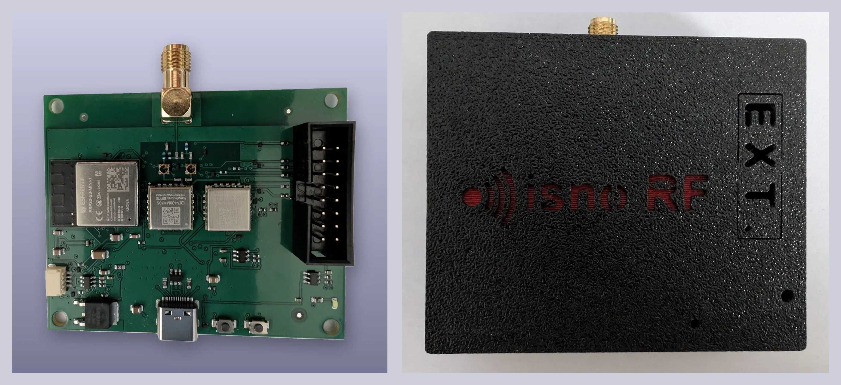
The Super is a board built to run firmware, and preferably radio firmware. It ships with its launcher: on first power-up it raises its own Wi-Fi access point, shows the state of its radios, and offers to install a firmware from the catalog or a file of your own, from a phone, with nothing plugged in but power. After that, it does whatever that firmware does, and the launcher takes back control if the image fails to boot. What it brings is the hardware these programs expect but never had: two CC1101 transceivers, at 433 and 868 MHz; an ESP32-S3 for compute, Wi-Fi and native USB; a Qwiic port and a mikroBUS for whatever you want to connect; all powered and programmed over USB-C. And alongside, a catalog of open firmware, checked against the board before being installed: OpenProfalux for roller shutters (Profalux on 868 MHz and Somfy RTS on 433 MHz today, more brands added over successive releases), OpenMQTTGateway for a gateway, more firmware to come. Home automation, Home Assistant first, is the first use. It is not the only one, and the board does not assume it.
This article tells how it is designed and why, what was calculated and what is now measured. The first five boards have arrived, bring-up passes (power, ESP32-S3, both CC1101) and the first RF bench measurements are done: the conducted emission of both radios, their harmonics, the receiver sensitivity.
Context
Several projects on this site start from the same point: an ESP32, a radio module costing a few euros, and eight jumper wires (OpenXtraflame keeps only the ESP32, it drives the stove over serial). It works, that is the goal, and the firmware will stay open. But when moving from a bench to an installation, you always end up in the same place: an 868 module for the Profalux shutters, a 433 module for the rest, two boards, two power supplies, two antennas, and nothing you could hand to someone else.
Looking at what exists, I counted about thirty open sub-GHz firmware projects for ESP32. Only a handful drive a CC1101, and no off-the-shelf board offers them two bands on a single antenna connector. Between the single-band bridge with closed firmware and the SDR dongle that receives everything and emits nothing, a gateway is missing.
The Super is that gateway. It is not a finished appliance: it is an open board on which you install the firmware of your choice, from a catalog that checks the firmware matches the board. That catalog, the launcher, is the second half of the product, and will be the subject of another article.
What is on it
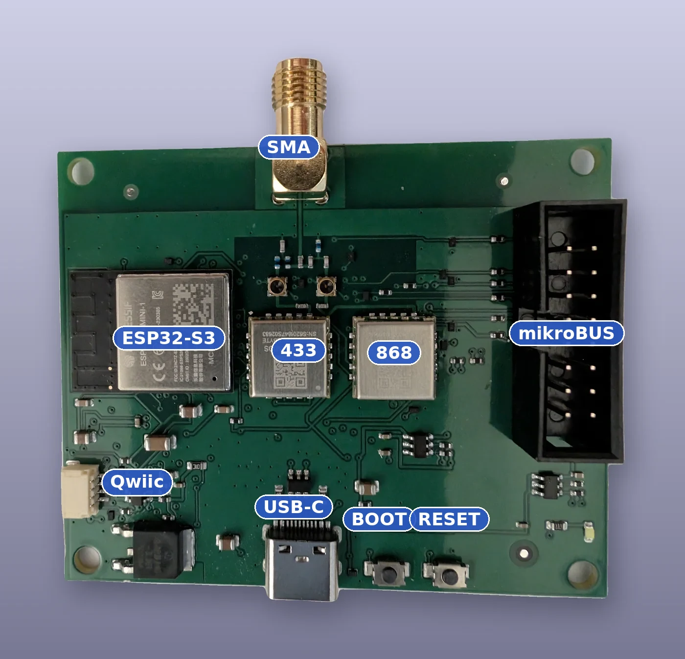
- ESP32-S3-MINI-1-N8, Wi-Fi and Bluetooth LE, native USB to flash without an adapter, integrated PCB antenna, and above all a proven industrial module.
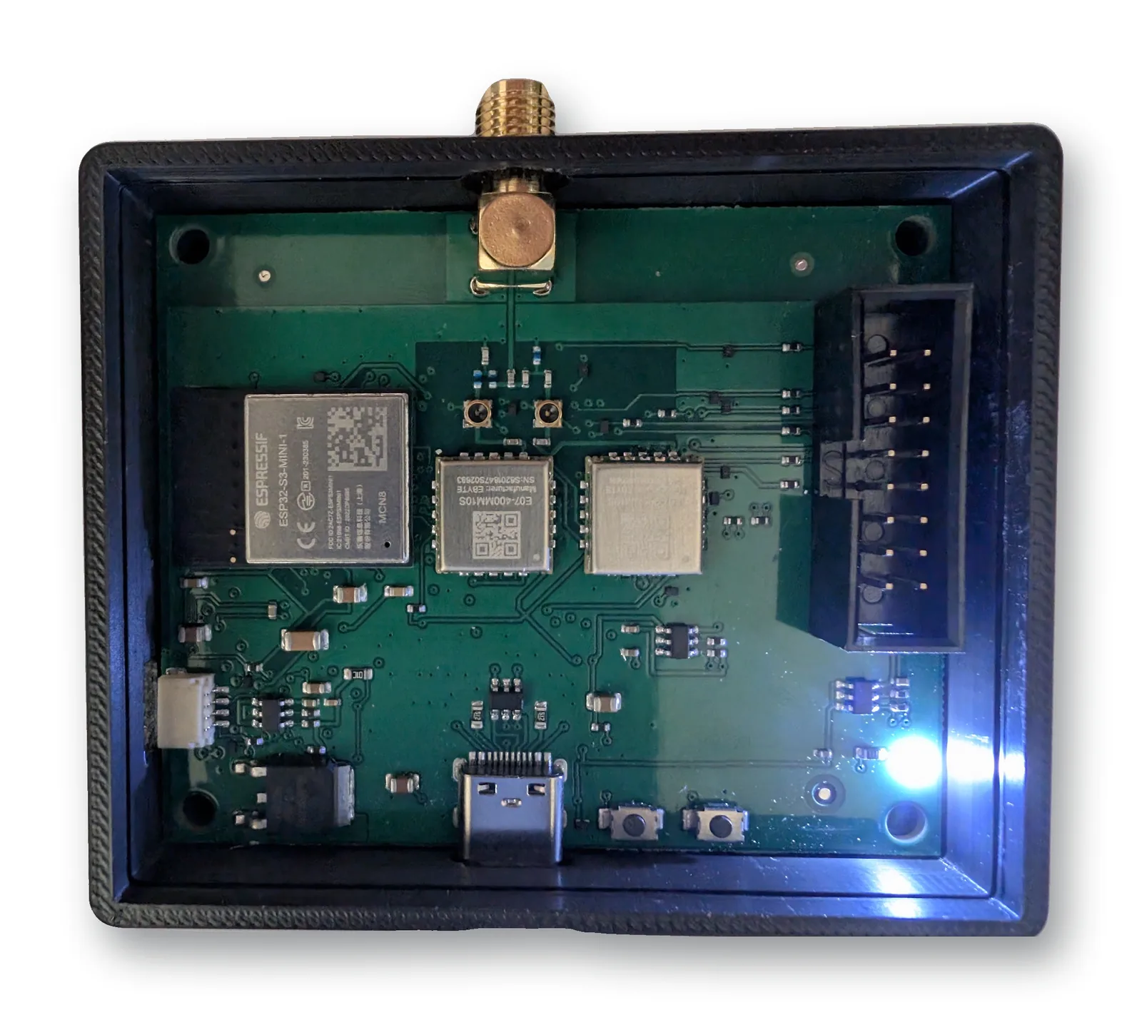
- Two CC1101 on E07 modules, an E07-900MM10S for 868 MHz and an E07-400MM10S for 433 MHz, 10 dBm each.
- Two RP-SMA connectors, one per band: each radio has its own. The EVT photographed above still combined both bands on a single connector; the board on sale no longer does, which removes the combiner losses and simplifies band-by-band measurement.
- A Qwiic port (STEMMA QT, 3.3 V I²C) and a keyed mikroBUS port (2x8), to connect a sensor or a Click board without soldering.
- USB-C for power and console, ESD protection on the USB and I²C lines, and a current limiter on each port power output. No mains connection.
- Two coaxial test switches Hirose MS-156C3, one per radio. They are there for the lab: plug in a probe and measure each radio’s conducted power without desoldering anything.
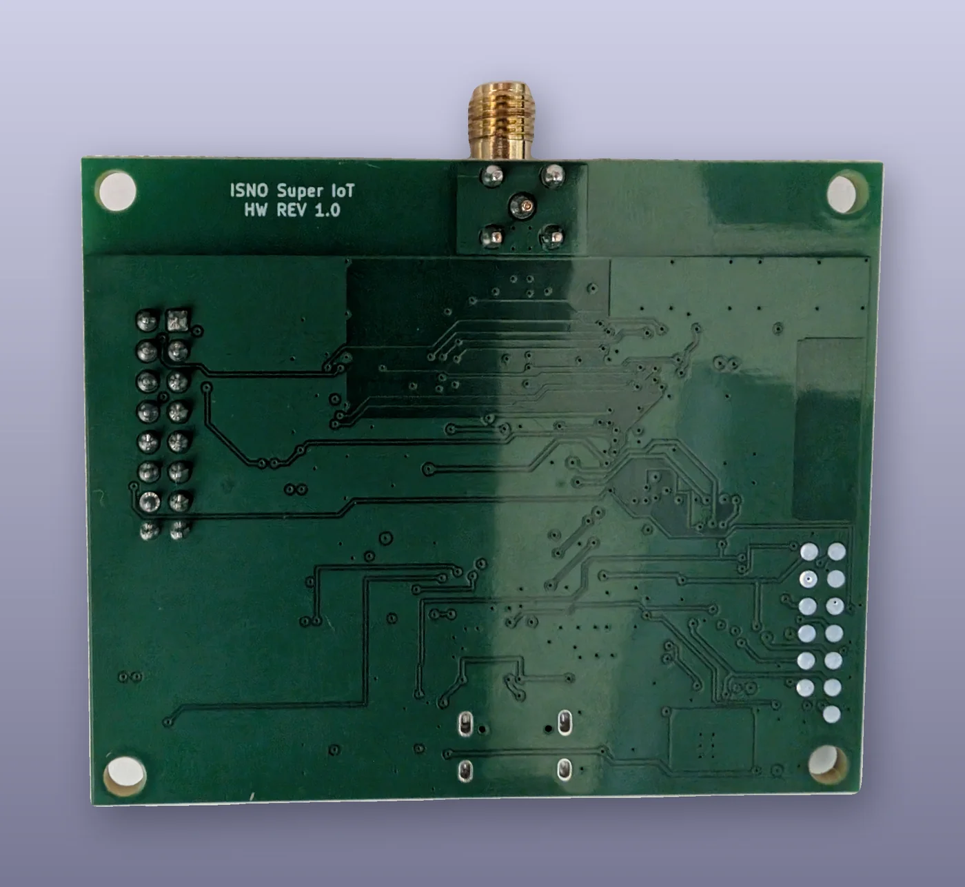
Four layers, RF lines in grounded coplanar waveguide at 50 Ω, longest RF trace 14 mm. The board is 67.4 x 55.3 mm, with four M3 holes at the corners.
The current budget, as calculated from the datasheets, to be confirmed on the bench:
| State | Current on 5 V |
|---|---|
| idle, Wi-Fi associated | 130 mA |
| Wi-Fi active | 260 mA |
| Wi-Fi transmit | 365 mA |
| Wi-Fi transmit and radio transmit at once | 405 mA |
| worst case kept for the regulator | 455 mA |
What the ports can draw, set by the three limiters: 151 mA on the Qwiic, 255 mA on the mikroBUS 3.3 V, 459 mA on its 5 V. The real ceiling is the USB source, 500 mA on an ordinary port: the board is made for a sensor or a Click board, not to power a motor.
The Super board, the mikroBUS riser and the corner adapter are on sale, subject to availability.
Functional diagram
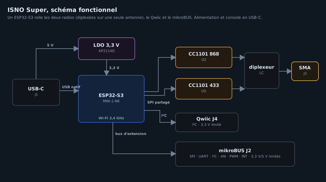
The two radios share the SPI bus and differ by their select and interrupt lines. The firmware activates only one transmitter at a time; both receivers listen continuously.
Pinout
What the launcher reads to check that a firmware addresses the right pins before installing it comes from the board declaration, itself taken from the manufacturing file, not copied by hand. The figure is derived the same way: positions and nets from the manufacturing file, GPIO numbers from the declaration.
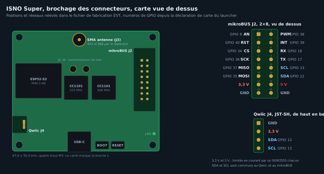
As on the OpenProfalux and OpenXtraflame articles: you wire by signal name, spotting pin 1 by its square pad, never by counting positions from an edge.
Radios, shared SPI bus
| Signal | GPIO | Radio 868 (U2) | Radio 433 (U5) |
|---|---|---|---|
| SCK | 4 | common | common |
| MISO | 5 | common | common |
| MOSI | 6 | common | common |
| CS | 7 | 15 | |
| GDO0 | 1 | 10 | |
| GDO2 | 2 | 11 |
Qwiic J4, 4-pin JST-SH: GND, 3.3 V, SDA on GPIO 12, SCL on GPIO 13. The 3.3 V is current-limited by a load switch. The mikroBUS has its own, one for 3.3 V and one for 5 V: three SGM2553 limiters in total, no fuse.
mikroBUS J2, keyed 2x8 connector:
| AN side | GPIO | PWM side | GPIO |
|---|---|---|---|
| AN | 8 | PWM | 38 |
| RST | 40 | INT | 39 |
| CS | 34 | RX | 18 |
| SCK | 36 | TX | 17 |
| MISO | 37 | SCL | 13 |
| MOSI | 35 | SDA | 12 |
| 3.3 V | current-limited | 5 V | current-limited |
| GND | GND |
A definitive pinout point to know: this mikroBUS connector is wired mirrored relative to the MikroElektronika Shuttle adapter. The ISNO adapters, the riser and the corner adapter, plug in directly and the right way round; however, connected by a straight ribbon cable to a Shuttle, 5 V would land on a reset line. On this board, you plug in a module, you do not run a straight ribbon cable.
The rest
| GPIO | Role | |
|---|---|---|
| BOOT button | 0 | download mode, and launcher button |
| LED | 26 | launcher and firmware indicator |
| UART | 17, 18 | console, also on the mikroBUS |
| USB | 19, 20 | D−, D+, native USB of the ESP32-S3 |
| board identification | 14, 47 | two straps read at boot, telling which variant is fitted |
| J5, J6 | Hirose MS-156C3 coaxial switches, one per radio, for the lab |
The two identification straps are what will let the single-radio variants be the same board with one module fewer: the firmware reads which are fitted and does not initialise what is missing.
What is checked before manufacturing
Before manufacturing, the board goes through a chain of automatic checks: design rules at zero errors, schematic-to-layout parity on 295 pins, a manufacturing review with no remark, and about thirty in-house validators on the RF traces, the ground plane, the regulator thermals and the bill of materials.
Two points verified by calculation:
- The regulator. An AP2114 in a DPAK package: 110 °C at maximum current, the datasheet’s conservative bound giving 131 °C. Modelled with 3D finite elements.
- USB start-up. The plug-in, the rise of 5 V, 3.3 V and the EN pin, run through ngspice. It is this calculation that caught a fault: a capacitor changed for another reason left the BOOT button unable to pull EN low enough, and each press caused a random reset. Fixed before manufacturing.
The prototypes
The five EVT boards arrived in late September 2026, manufacturing review passed and placement confirmation signed on 15 September. The first, #0001, goes through its bring-up: clean power with no short, ESP32-S3 recognised over native USB, and both CC1101 answering at 433 and 868 MHz.
The bench measurements
The first RF measurements now exist: a first series taken on the bench on the EVT board, each radio in turn, on the spectrum analyser. These are engineering measurements, taken on the bench.
See the bench measurements (October 2026)
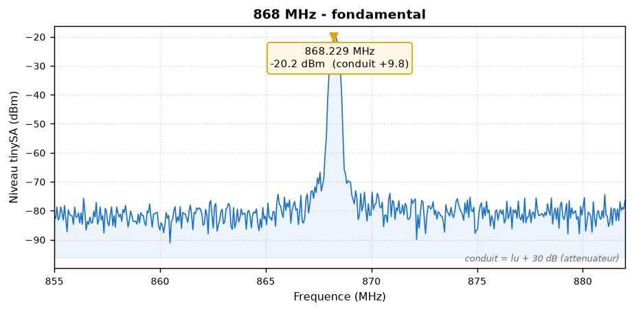
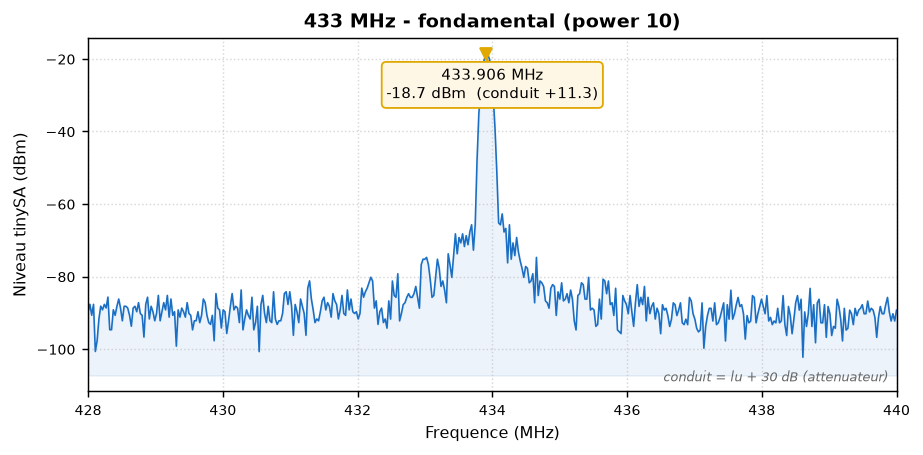
The two fundamentals, measured at the SMA connector: each radio puts out a clean carrier.
Conducted power (tinySA reading plus 30 dB attenuator), by the power setting:
power | 433 | 868 | 915 |
|---|---|---|---|
| 5 | +2.3 dBm | +2.8 dBm | +3.1 dBm |
| 7 | +8.3 dBm | +6.3 dBm | +4.6 dBm |
| 10 | +11.8 dBm | +9.3 dBm | +7.6 dBm |
Harmonics. The 868 and 915 are clean: harmonics below the floor, more than 65 dBc. The second harmonic of the 433 falls in the 868 band: this is what leads to setting the 433 around 8 dBm rather than 10.
Occupied bandwidth (2FSK modulation): 12.7 kHz at 868, 13.0 kHz at 433. Very narrow.
Frequency error: -14.9 ppm at 868, -11.3 ppm at 433, within the crystals’ tolerance and far from the band edges.
Receiver sensitivity: floor -116 dBm at 433, -112 dBm at 868, -118 dBm at 915. Sensitive and healthy.
915 variant (US): the 868 chain passes 915 at +7.6 dBm conducted, clean harmonics. The EVT board therefore also works at 915, without changing a component.
Twelve open points are recorded in a dated errata. The non-cosmetic ones:
- the antenna is not chosen: the radio modules’ reference antennas are 3.5 dBi, a gain too high for the 433 at the measured power: a low-gain antenna will be needed;
- the lid opening above the mikroBUS is cut for a bare flat plug, and a cable-gland plug does not fit;
- the prototype silkscreen is empty, no connector is named on it.
These open points are therefore marked in the repository itself: publishing a design with an undocumented trap is not open hardware.
More measurements will follow on the five boards, and a next revision will fix the open points.
Openness
The board design is licensed under CERN-OHL-S version 2, the strongly reciprocal variant:
whoever manufactures from these files must publish their modifications. The repository is open:
OpenSuperRF holds the KiCad sources of the v1.0 (EVT),
the EVT fab and the RF measurements, with the open points marked in a dedicated file
(KNOWN_ISSUES.md).
What’s next
- RF868, the single-band variant, derived from the Super by subtraction: remove the 433 radio and what only serves it, keep everything that is proven. It will come next.
- The launcher and its catalog, which install third-party firmware on the board from the browser, with, for each entry, the proof that its pins and bands match the declared board. A separate article.
- The pre-order is open: pre-order the Super. 69.90 € plus shipping, and it is what sets the size of the first batch: a threshold of 35 triggers manufacturing.